INNOVOTEK
A blog about the news of the latest technology developments, breaking technology news, Innovotek Latest news and information tutorials on how to.
Analog and Mixed Signal Modeling Approaches
- Font size: Larger Smaller
- Hits: 10472
- 0 Comments
- Subscribe to this entry
- Bookmark
 1 Abstract
This article provides an insight into various approaches followed for Analog and Mixed Signal (AMS) modeling and the associated challenges. The emphasis is on analyzing various approaches and finally providing options that can be used right from architectural exploration to implementation with a co-simulation based approach.
2 Introduction
In today’s world, AMS models are used for architecture exploration and performance evaluation. The AMS models are also used in place of mixed signal IPs for faster simulation in co-simulation environments. The conventional co-simulation approaches are time consuming with respect to setup and execution. The article starts highlighting the challenges involved in AMS designing and modeling, and then different modeling techniques are explained in brief including SystemC AMS with a case study of DPLL model in the end.
3 Challenges in AMS Design and Modeling
- Design stability in AMS systems is achieved after the design is simulated across all the corners and at all Process, Voltage and Temperature (PVT) conditions.
- Simulators which support AMS simulation are expensive and slow. In addition, co-simulation setup is a time consuming process.
- Modeling AMS system involves tradeoff between simulation time and accuracy.
- Simulink and Ptolemy can capture continuous time behavior, but do not target the design of AMS systems at an architecture level.
- HDL’s like VHDL-AMS and Verilog-AMS target the design of mixed signal subsystems close to implementation level, but these languages have limited capabilities to provide efficient HW/SW co-design at high level of abstraction.
- There is a lack in offering seamless design refinement flow for mixed-signal discrete event/continuous time systems and HW/SW systems at architecture level.
4 Analog and Mixed Signal Modeling Approaches
VHDL-AMS, Verilog-AMS and SystemC-AMS allow modeling of discrete and continuous-time signals or a combination of both. All the three afore said HDL languages can represent AMS systems at a higher level of abstraction by bringing down the simulation time while providing the intended functionality of the design. The following sections describe the process of modeling in each of the languages and finally a comparison of all the available modeling options to give a clear understanding of the pros and cons of each language.
4.1.1 VHDL – AMS
VHDL-AMS is an extension of VHDL to model AMS circuits and systems. Both electrical and non-electrical systems can be described at different levels of abstraction using VHDL-AMS. The VHDL – AMS cycle starts with initialization phase, which consists of the following main steps.
- Computation of initial values of the driving signals, and quantities defined by attributes.
- Process execution until they are suspended.
- End of processes execution and setting simulation time to zero.
Both Verilog-A and SystemC-AMS follow a similar initialization technique. The actual VHDL-AMS simulation cycle begins with the computation of analog solution points (arrow 1 in Figure 1). This continues until the next digital event is scheduled or an event occurs on the analog and digital interface (arrow 2 in Figure 1). To compute a digital evaluation point, signals are updated first. After that, any triggered processes are executed until they settle. If the time for the next digital evaluation Tn is equal to current time Tc, the digital simulator is called again (arrow 3 in Figure 1). If Tn is not equal to Tc, the analog solver is called, and the next cycle begins (arrow 4 in Figure 1). This continues until the end of simulation is reached (arrow 5 in Figure 1).
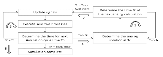
Figure 1: VHDL-AMS simulation cycle – Execution
4.1.2 Verilog – A
Verilog – A allows the designer to capture the behavior of AMS designs at different levels of abstraction. Figure 2 indicates the typical Verilog – A simulation cycle.
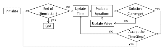
Figure 2: Verilog – AMS Simulation Cycle
- Initialization: The initialization phase of a transient analysis is the process of initializing the circuit state at time zero.
- Synchronization: A Verilog-A simulation consists of a number of analog and digital processes communicating via events, shared memory and conservative nodes. All conservative nodes (macro process) are represented by matrices and solved jointly.
- Evaluation: The design description consists of differential and non-linear equations which are discredited and solved iteratively.
- Update: Analog processes are sensitive to changes in all variables and digital signals read by the process unless that access is only in statements guarded by event expressions. Upon waking up, the process computes a new solution point, schedules its next wake up event appropriately and then deactivates itself.
- Convergence: In analog kernel, the behavioral description is evaluated iteratively. On the first iteration, the signal values used in the expressions are approximate. As the iterations progress, the signal values approach the solution. Iterations continue until the difference between two consecutive solutions is less than an absolute tolerance value and the Kirchoff’s flow laws are satisfied.
4.1.3 MATLAB - Simulink
MATLAB - Simulink or other interpretation tools can be used to model AMS systems if supporting libraries and functions are available. Simulink has an inbuilt analog tool set which can be used for AMS modeling and the accuracy results are comparable to that of spice simulation results. At higher levels of abstraction, this can be used for architectural exploration where the feasibility of a particular architecture and its functionality through simulations can be explored. The high cost of simulators, the increase in simulation time as the level of design abstraction reduces and problems with co-simulation make Simulink a non-preferred flow for AMS designs.
4.1.4 SystemC – AMS
SystemC-AMS is an extension of SystemC that uses an open and layered approach. The base layer is the existing SystemC 2.0 kernel. On top of the base layer, two sets of layers are defined: Interface to the existing SystemC layers, (e.g., discrete event channels), and a new set of AMS layers such as the synchronization layer, the solver layer, and the user layers.
The user view layer provides methods to describe the continuous-time models in terms of procedural behavior, equations, transfer functions, state-space formulations, and as netlists of primitives. Due to its open source architecture, the user can add additional features to the simulator depending on their application. SystemC-AMS uses a Synchronous Data Flow (SDF) model of computation for modeling and simulation.
The solver layer provides different implementations of solvers (such as linear solver to solve electrical network) that are required to simulate specific AMS descriptions.
The synchronization layer implements a mechanism to organize the simulation of a SystemC-AMS model that may include different continuous-time and discrete event parts. SystemC-AMS defines a generic interface for various continuous-time solvers and provides methods to synchronize analog solvers and the discrete kernel of SystemC.
SystemC AMS extensions are not intended to replace circuit simulators. The use of more accurate circuit simulators to verify circuit implementations can be applied, once an integration of a circuit simulator is available.
4.1.4.1 Advantages of SystemC-AMS
- Abstract definition: SystemC provides a means for modeling and simulation of systems that is more abstract than HDLs for AMS systems.
- Accuracy: Maintains acceptable simulation accuracy while modeling architecture’s behavior with sufficient accuracy.
- Extensibility:
- The AMS extensions provide a standard formalism for modeling of AMS architectures that bridges the gap between functional modeling frameworks and HDLs used for implementation.
- SystemC AMS extensions allow the industry or EDA vendors to integrate “user defined extensions” to support different domains such as modeling for telecommunication, automotive or sensor imaging techniques.
- Cost
- System level tools like Ptolemy and Simulink are often used for functional modeling and simulation are very expensive.
- The tools required to compile and execute for SystemC AMS are available as Open source.
- Limitations of conventional approaches for AMS modeling.
- Interoperability: Independent of standard Simulator.
- Ease of use as most of the engineers are familiar with C language as SystemC is an extension of C and C++.
- Trace and Debug: In addition to a means of modeling linear signal flow, timed data flow and electrical linear networks, the SystemC extensions provide a means for tracing signals like HDLs.
4.1.4.2 SystemC-AMS Flow
The SystemC-AMS simulation cycle is shown in Figure 3 and is summarized below:
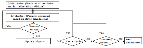
Figure 3: SystemC – AMS Simulation Cycle
- Step 1: Initialization - The initialization methods registered in SystemC-AMS modules are executed including the initial condition definitions.
- Step 2: Evaluation - Processes are only executed at delta 0 in the order defined by the static scheduling (delta cycles provide a standard way to emulate concurrency when simulating discrete-event models). The cluster processes will be reactivated, always at delta 0, at every time step defined for the cluster.
- Step 3: Repeat Step 2 while there are still processes ready to run, else go to Step 4.
- Step 4: Update - Signals are updated with their new values.
- Step 5: Go to Step 2 if the updated signal generates events with zero delay (delta cycle), else go to Step 6.
- Step 6: Finish simulation if there are no more pending events, else go to Step 7.
- Step 7: Advance the time to the earliest pending event.
- Step 8: Determine ready to run processes and go to Step 2.
4.1.4.3 SystemC Applications
- Executable specification at functional level:
This is created to verify the correct understanding of the system specification by simulation. For this use case, data flow and signal flow are appropriate modeling styles. The executable specification can have structures and algorithms that are hard to subsequently change or modify later. Therefore, structure and algorithms that match the architecture should be chosen carefully. - Architecture exploration at functional level and implementation level:
The architectural exploration stage evaluates and determines the key parameters at initial specification level. It is structured in two phases: In the first phase, the executable specification is refined by adding the non-ideal properties of an implementation to get a better understanding of their impact on the overall system behavior. In the second phase, the architecture’s structure and interfaces are adapted to match the final implementation to get a more accurate model. - Integration validation:
For integration and validation, the interfaces of all subsystems must be modeled accurately: The interfaces and data types used in the models should match the implementation. For analog circuits, this relates to electrical nodes. After the design definition of analog, digital HW/SW components, the components are integrated and their correctness is verified within the system. - Virtual prototyping:
Virtual prototyping provides software developers with a high-level un-timed or timed model that represents the hardware architecture. Especially, for Embedded AMS systems, where software is interacting with AMS hardware, interoperability of SystemC TLM extensions is important.
5 Modeling Approaches and performance trade-off
The block diagram of different modeling approaches for AMS design is as shown in Figure 4.
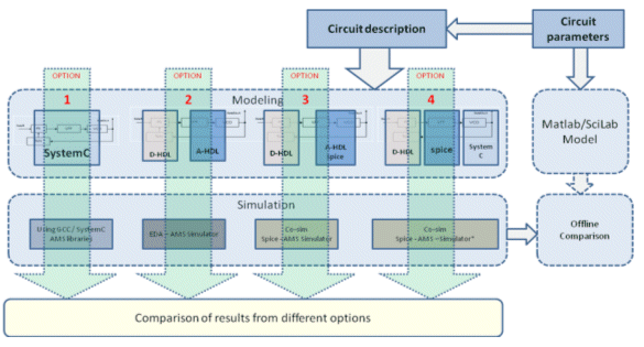
Figure 4 : AMS modeling Approaches
Table 1 provides information about the comparison of various parameters for each of the approaches used for AMS systems. The main parameters considered are accuracy, abstraction level, time required for modeling the system, simulation times, tools required and the support.
| Parameter | VHDL-AMS | Verilog-A | SystemC-AMS | SPICE |
| Accuracy | Med – High | Med - High | Med - High | High |
| Abstraction Level | Any abstraction level | Any abstraction level | Any abstraction level | Transistor / Netlist level |
| Time to model | Less to Medium | Less to Medium | Less | High |
| Simulation Run Time | Less | Less | Medium - High | High |
| Tools required | Simulator | Simulator | AMS libs with GCC/ Simulators | Simulators |
| Support | Available | Available | Less | Available |
Table 1: Modeling approaches and performance trade-off.
6 Case study: Digital Phase Locked Loop (DPLL)
This section takes example of the DPLL and explains how a system can be modeled using the available modeling options. A typical DPLL as shown in Figure 5; it consists of four main blocks: a phase detector, a low pass filter, a VCO and a modulo N-bit divider. The actual implementation consists of the phase detector (PD) using XOR gate and a low pass filter (LPF) using a RC network. Each of these components can be modeled using SystemC AMS, VHDL-AMS, Verilog-A and Spice, with respective digital components being modeled either in SystemC, VHDL or Verilog. Table 2 shows the available options for modeling of DPLL.
- Option 1: Complete system implemented using SystemC AMS.
- Option 2: The digital portion (PD and divider) can be implemented using VHDL/Verilog and the rest of the system in Verilog-A or VHDL-A.
- Option 3: The PD and divider are implemented using VHDL/Verilog, LPF implemented in Spice and VCO implemented in VHDL-A or Verilog-A.
- Option 4: The digital portions (PD and divider) are implemented in VHDL / Verilog, the LPF in Spice and VCO using SystemC AMS; this option also enables co-simulation using SystemC AMS through industry standard simulators.
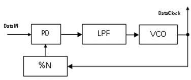
Figure 5: Block diagram of DPLL
The following table shows various components of DPLL along with available options in which the system can be implemented. Four variants of implementation are available with the available modeling languages and tool set.
| Component | PD and %N | LPF | VCO | Comments |
| Option 1 | SystemC-AMS | SystemC-AMS | SystemC-AMS | Using GCC / SystemC AMS libraries |
| Option 2 | VHDL / Verilog | VHDL-A / Verilog-A | VHDL-A / Verilog-A | Using EDA – AMS Simulator |
| Option 3 | VHDL / Verilog | Spice | VHDL –A / Verilog-A / Spice | Co-simulation using Spice and EDA simulator |
| Option 4 | VHDL / Verilog | Spice | SystemC AMS | Co-Simulation if simulator* supports SystemC AMS |
Table 2: Various Options to model DPLL
7 Conclusion
The study of various modeling options available for AMS systems provided an opportunity to explore the different architectures with an emphasis on co-simulation and parameters like accuracy, time to model, simulation time etc. It is recommended to use an appropriate approach based on the criticality of parameters and usage of application. For example, SystemC AMS provides a platform for architectural exploration of AMS systems supported by AMS libraries and uses open source tools (like gcc, gdb etc) and less time to model while improving the simulation speed.